
31. Model Uncertainties#
List of Symbols
\(\begin{array}{ll}Y & = \text { response of the structure according to the model } \\ Y^{\prime} & = \text { real response of the structure } \\ f() & = \text { model function } \\ f^{\prime}() & = \text { model function including model uncertainties } \\ X_{\mathrm{i}} & = \text { basic variable } \\ \theta_{\mathrm{i}} & = \text { model uncertainty }\end{array}\)
31.1. General#
In order to calculate the response of a structure with certain (random) properties under certain (random) actions use is made of models (see Part I, section 5). In general such a model can be described as a functional relation of the type:
\(Y =\) response of the structure
\(f()=\) model function
\(X_{i}=\) basic variables (actions and structural properties)
The model function \(f(..)\) is usually not complete and exact, so that the outcome \(Y\) cannot be predicted without error, even if the values of all random basic variables are known. The real outcome \(Y^{\prime}\) of the experiment can formally be written down as:
The variables \(\theta_{i}\) are referred to as parameters which contain the model uncertainties and are treated as random variables. The model uncertainties account for:
random effects that are neglected in the models
simplifications in the mathematical relations
Ideally model uncertainties should be obtained from a set of representative laboratory experiments and measurements on real structures where all values of \(x_{i}\) are measured or controlled. In those case a model uncertainty has the nature of an intrinsic uncertainty. If the number of measurements is small the statistical uncertainty may be large. Additional there may be uncertainty due to measurement errors both in the \(X_{i}\) and in the \(Y\). Bayesian regressian analysis usually is the appropriate tool to deal with the above situation.
In many cases, however, a good and consistent set of experiments is lacking and statistical properties for model uncertainties are purely based on engineering judgement. Sometimes a comparison between various models may help to defend certain propositions.
The most common way of introducing the model uncertainty into the calculation model is as follows:
or
or a combination of both. The first definition is clarified in Fig. 31.1
It should be kept in mind that this way the statistical properties of the model uncertainties depend on the exact definition of the model output. A theoretical elegant way to avoid these definition dependency is to link model uncertainties directly to the basic variables, that is to introduce \(X^{\prime} i=\theta_{1} X_{i}\)
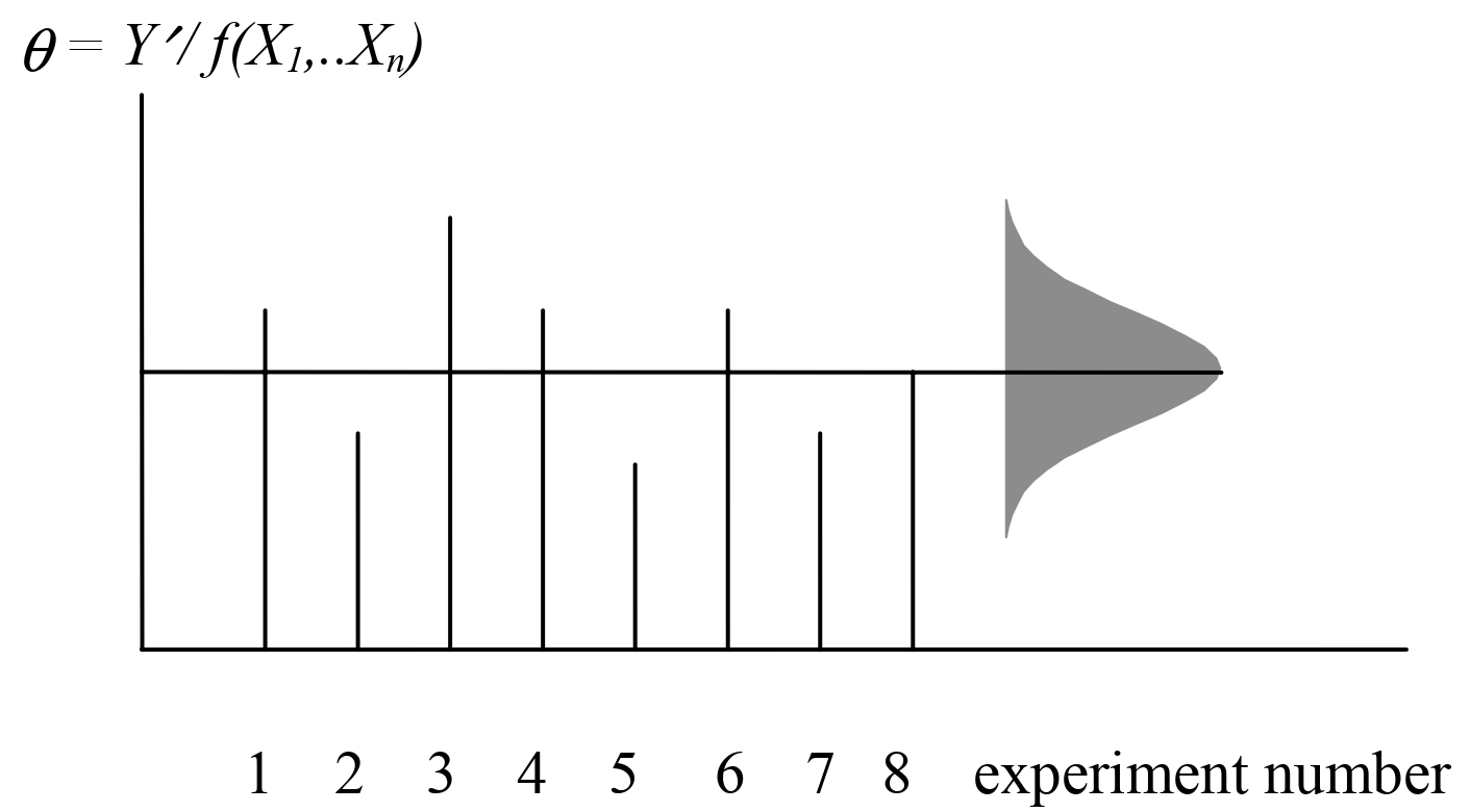
Fig. 31.1 estimation of model uncertainty statistics on a number of tests following definition 31.3.#
31.2. Types of models for structural analysis#
Model uncertainties can be subdivided into:
load calculations models
load effect calculation models
local stiffness and resistance models
For the model uncertainties in the load models reference is made to Part 2.
The load effect calculation models have to do with the linear or nonlinear calculation of stresses, axial forces, shear forces and bending and torsional moments in the various structural elements. The model uncertainties are usually the result of negligence of for example 3Deffects, inhomogenities, interactions, boundary effects, simplification of connection behaviour, imperfections and so on. The scatter of the model uncertainty will also depend on the type of structure (frame, plates, shell, solids, etc).
The local models are used to define the behaviour of an element, a typical cross section or even of the material in a single point. One may think in this respect of the visco-elastic model, the elastic plastic model, the yield condition (Von Mises, Tresca, Coulomb), the hardening and softening behaviour, the thermal properties and so on.
31.3. Recommendations for practice#
Models may be of a numerical , analytical or empirical nature. In the recommended values in Table 31.1 a more or less standard structural Finite Element Model has been kept in mind.
The model uncertainties are assumed to be partly correlated throughout the structure: on one point of the structure the circumstances will usually be different from another point which makes it unlikely that a full correlation exists. For that reason the Table 31.1 also includes an estimate for the degree of correlation between various points or critical cross sections in one structure.
Model type |
Distr |
mean |
CoV |
correlation |
|---|---|---|---|---|
load effect calculation |
|
|
|
|
resistance models steel (static) |
|
|
|
|
resistance models concrete (static) |
|
|
|
(1) including the effects of normal and shear forces.